Arduino Shield L298P Motor Driver with GPIO
Ei tuotteita
Moottoriohjaimet
- 3D-tulostus
- Antennit
- Akut ja paristot
- Arduino
- Audio/video
- Autoilu
- Automaatio
- BBC micro:bit
- Elektroniikan komponentit
- Anturit
- Aktiivit
- Passiivit
- Komponenttilajitelmat
- Hälytin/valvonta
- IOT
- Juottaminen
- Juottimet
- Juotintelineet
- Juoksutteet/pastat
- Juotoslangat
- Juottamisen apuvälineet
- Kaasujuottimet
- Kuumailma-asemat
- Pintaliitostekniikka
- Puhdistustarvikkeet
- Tinaimurit ja tinaimusukat
- Varaosat Pace
- Varaosat Proskit
- Varaosat Thermaltronics
- Varaosat Velleman
- Varaosat Weller
- Varaosat Xytronic
- Sekalaiset juotostarvikkeet
- Varaosat Pinecil
- Varaosat Atten
- Kaapelit metritavarana
- Antennikaapelit 50ohm
- Antennikaapelit 75ohm
- Audiokaapelit/johdot
- Datakaapelit
- FFC kaapelit
- Kaiutinkaapelit
- Kalustekaapelit
- Kumikaapelit
- Kuparilangat
- Lattakaapelit
- Monisäikeiset asennusjohdot
- Puhelinkaapelit
- Silikonijohdot
- Termoparikaapelit
- Verkkokaapelit CAT5/6/7
- Videokaapelit
- Yksisäikeiset kytkentäjohdot
- Kaapelilajitelmat
- Virransyöttökaapelit
- Kaapelitarvikkeet
- Kehityskortit
- Kirjat
- Ledit
- Liittimet
- Audio/video-liittimet
- Autoliittimet
- Piikkirima-liittimet
- RJ modular-liittimet
- Puristusliittimet
- RF-liittimet
- 7/16-koaksiaaliliittimet
- BNC-liittimet
- F-liittimet
- FME-liittimet
- IEC-antenniliittimet
- MCX-liittimet
- MMCX-liittimet
- MiniUHF-liittimet
- N-liittimet
- SMA-liittimet
- SMB-liittimet
- SMC-liittimet
- SSMB-liittimet
- TNC-liittimet
- UHF-liittimet
- U.FL-liittimet
- RF-testiliittimet
- RF-välikaapelit
- Sekalaiset koaksiaaliliittimet
- Riviliittimet
- Teollisuus-liittimet
- Data-liittimet
- Virtaliittimet
- Liitinadapterit
- Lämmönhallinta
- Mekaniikka
- Näytöt
- Mittalaitteet
- Yleismittarit
- Mittajohdot/liittimet
- Paneelimittarit
- Pihtimittarit
- Jännitekoettimet
- Lämpömittarit
- Ympäristön mittalaitteet
- Keinokuormat
- Komponenttitesterit
- Kuituverkon mittaus
- Sähköverkon mittaus
- Debuggaus
- Oskilloskoopit
- Signaaligeneraattorit
- Sekalaiset mittalaitteet
- Spektrianalysaattorit
- Logiikka-analysaattorit
- Probet
- Dataloggerit
- Mittalaitetarvikkeet
- Rigol oheistarvikkeet
- Rigol optiot
- Muistikortit
- Palvelut
- Puhelimet
- Protoilu
- Rakennussarjat
- Raspberry Pi
- Raspberry Pi 5
- Raspberry Pi 4 asti
- Raspberry Pi Compute Module
- Raspberry Pi 400 / 500
- Raspberry Pi Pico
- Raspberry Pi Zero
- Raspberry Pi aloitussarjat
- Raspberry Pi tapaiset tietokoneet
- SBC näytöt
- SBC lisäkortit
- SBC hifikortit
- SBC tarvikkeet
- SBC kotelot
- SBC kamerat
- SBC sekalaiset
- SBC kirjat
- SBC muistikortit
- SBC räkkiasennus
- Retro gaming
- Robotit
- Sekalaiset
- Sähkömekaniikka
- Kytkimet
- Painokytkimet
- Vandal proof painokytkimet
- Arcade pelikytkimet
- Keinukytkimet
- Liukukytkimet
- Mikrokytkimet
- Ovikellokytkimet
- Pulssienkooderit
- Rockwell teollisuuskytkimet
- Vipukytkimet
- Asentokytkimet
- Avainkytkimet
- DIP-kytkimet
- Jalkakytkimet
- Joystick
- Kalustekytkimet
- Kalvokytkimet
- Kiertokytkimet
- TV-verkkokytkimet
- Lamput
- Moottorit
- Releet
- Solenoidit
- Sulakkeet
- Tulppasulakkeet
- WICKMANN-sulakkeet
- Yleismittarisulakkeet
- Ylikuormitussuojat
- Autosulakkeet
- HRC-sulakkeet
- Lämpösulakkeet
- Langalliset sulakkeet
- Lasiputkisulakkeet
- Mikroaaltouunin sulakkeet
- Minisulakkeet TR5
- Palautuvat ylivirtasuojat
- Picosulakkeet
- Pintaliitossulakkeet
- Puolijohdesuojat
- Sulakepesät
- Sulakelajitelmat
- Kahvasulakkeet
- Termostaatit
- Kontaktorit
- Kytkimet
- Sähkötarvikkeet
- Teholähteet
- Tietokonetarvikkeet
- Tietoliikenne
- Ethernet/LAN
- RJ45-liittimet/rasiat
- Verkkokaapeloinnin työkalut
- Ethernet tarvikkeet
- Ethernet verkkokaapelit
- RJ45-moduulit
- SLIM® CAT6 Ethernet kaapelit
- SLIM® CAT6 Patchcords FLAT U/UTP
- SLIM® CAT6 Patchcords FLAT U/FTP
- SLIM® CAT6A Patchcords FLAT U/FTP
- SLIM® CAT6 Patchcords ROUND U/UTP
- SLIM® CAT6 Patchcords ROUND U/FTP
- SLIM® CAT6A Patchcords ROUND U/FTP
- SLIM® CAT6 Patchcords FLAT U/UTP with Nylon sheath
- SLIM® CAT6 Patchcords FLAT U/FTP with Nylon sheath
- Kytkentäpaneelit
- Valokuidut
- SFP Transceiverit
- WiFi
- Ethernet kytkimet
- Ethernet mediamuuntimet
- Reitittimet
- Yhdyskäytävät
- Ethernet/LAN
- TV/radio/VCR/CD
- Työkalut
- Valaistus
- Vimpaimet
- Edustukset Elgood Oy
- Abiko
- Adda
- Arduino Pro
- Attend
- Belden
- Blueferrite
- Broadlake
- Cvilux
- Danotherm
- DECA
- Delta
- Dinkle
- Entertec
- Finder
- Finder 12 Series
- Finder 13 Series
- Finder 14 Series
- Finder 1C Series
- Finder 20 Series
- Finder 22 Series
- Finder 34 Series
- Finder 36 Series
- Finder 38 Series
- Finder 39 Series
- Finder 40 Series
- Finder 41 Series
- Finder 43 Series
- Finder 46 Series
- Finder 48 Series
- Finder 4C Series
- Finder 58 Series
- Finder 50 Series
- Finder 55 Series
- Finder 56 Series
- Finder 60 Series
- Finder 62 Series
- Finder 65 Series
- Finder 66 Series
- Finder 68 Series
- Finder 7H Series
- Finder 7L Series
- Finder 7M Series
- Finder 7T Series
- Finder 80 Series
- Finder 83 Series
- Finder 86 Series
- Finder 8A Series
- Finder 90 Series
- Finder 92 Series
- Finder 93 Series
- Finder 94 Series
- Finder 95 Series
- Finder 96 Series
- Finder 99 Series
- Fulham Company B.V
- Geehy
- Hengstler
- Hirose
- HolyStone
- Jianghai
- KDS
- Lantronix
- Linear Integrated Systems
- LinkPP
- Luminus
- Murata
- Myrra
- PeakTech
- Provertha
- Quectel
- Relpol
- Rigol
- Rigol oheistarvikkeet
- Rigol optiot
- Rigol DG800 Pro
- Rigol DG900 Pro
- Rigol DG1000Z
- Rigol DG4000
- Rigol DG5000 Pro
- Rigol DHO800
- Rigol DHO900
- Rigol DHO1000
- Rigol DHO4000
- Rigol DHO5000
- Rigol DL3000
- Rigol DM3000
- Rigol DP700
- Rigol DP800
- Rigol DP900
- Rigol DP2000
- Rigol DS1000Z
- Rigol DS2000
- Rigol DSA700
- Rigol DSA800
- Rigol DSG800
- Rigol MHO2000
- Rigol MHO5000
- Rigol MSO5000
- Rigol MSO7000
- Rigol MSO8000A
- Rigol RSA3000
- Rigol RSA5000
- Seiko
- Sensepeek
- Sensolute
- Teltonika Networks
- Teltonika Telematics
- VAC
- Winstar
- wireless-tag
- WKK
- Uutiskirjeet
- Kampanjat
- Välitysmyynti
-

Rigol DP832A TEHOLÄHDE 195W 2x 0-30V/3A, 0-5V/3A
Rigol DP832A - kolmikanavainen,...
532,31 € -15% 626,25 €
Description
This Motor Driver Shield based on L298P motor driver IC is capable of driving two brushed motor, with speed, direction, start and stop simultaneously. With two full H-bridge circuit, this motor driver shield can also drive bipolar or unipolar stepper motor.
Besides the L298P driver IC, it comes with tones of header pins and female header for GPIO of Arduino. The ADC pins of Arduino main board are being extended to SVG (Signal Voltage Ground), RC servo alike header pins. Making it simple for you to connect to sensor module with the extra pin of GND and 5V.
Not to forget there are two types of Bluetooth module, mainly the HC05 or HC06. Another type bluetooth connector is seldom being utilized.
This multi-featured motor shield based around the L298P driver chip fits onto Arduino Uno or other Arduino UNO compatible boards.
Features
- Drive two DC motors at 4.8-24V at up to 2A peak(1.0 continuous max) current
- Built-in Schottky diodes to protect against motor back EMF
- Drive 1 servo motor with a dedicated 5V regulated power
- Built-in buzzer connected to D4, active high
- Extra push button as Arduino reset switch
- Bluetooth connector (x2)
- Ultrasonic Range Finder Ping socket for SR04 (Ping and Echo)
- RGB LED connector
- 6 analog/digital pins(A0 to A5) brought out to 3-pin headers(SVG) with 5V and Gnd available for each input for easy sensor hookup
- Stacking female connectors for supporting another daughter card
- Can optionally power attached Arduino off the shield
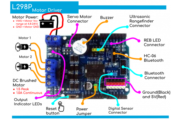
Logic Power subsystem
The Arduino's 5V is brought up to the shield and is available on:
- 6 sets of red sensor 5V pins(SVG) for Analog pin
- Yellow Ping connector for Ultrasonic Rangefinders
- Two blue digital connectors
- Used to power the logic portion of the L298P chip.
This ensures that they have good clean 5V power independent of what the motors are doing.
The Arduino's 3.3V is brought up to the shield and is available on the 2 Bluetooth connectors.
Arduino main board can be powered separately using the normal USB or DC power connector or alternatively, it can also be powered from this Shield. To select this power path, there is a jumper near the electrolytic cap labeled ‘OPT’. When this jumper is removed, the Arduino must be powered separately. When the jumper is installed, the power from the motor VMS power connector is connected to the Vin pin on the Arduino which feeds the Arduino on-board 5V regulator. To use this option, the motor power input must be at least 6.5VDC and less than 12VDC to feed the regulator. If powering the Arduino off the shield, the DC power jack on the Arduino should not be used to avoid a power conflict, but the USB can be used.
Motor Power Subsystem
The motor power comes in on the 2-pos screw terminal. The VMS is the positive motor voltage which can range from 4.8 to 24VDC. If you are using this input to power the Arduino by installing the ‘OPT’ jumper, the maximum input voltage on this terminal should be limited to 12V to avoid overheating the Arduino regulator.
- VMS = Motor Vcc which must be between 4.8 and 24VDC
- GND = Motor Ground
This motor power is fed to a 5V regulator that is mounted to the bottom of the shield. This 5V feeds the white servo connector(near to buzzer). This isolates any servo electrical noise from getting back into the main 5V that powers the logic. For this 5V regulator to function, the VMS voltage must be at least 6.3V and limited to 12VDC max to avoid heat to the 5V regulator.
Note: If you have the OPT jumper in place and USB connected, but there is no power on the VMS motor connector, it will try to use the USB power to power the DC motors. This should be avoided.
If you have the OPT jumper in place and power coming on the DC Jack on the Arduino, it will work but the DC motor noise will be coupled into the 5V logic power supply and may cause eradicate behavior and so it is not really recommended. In general, if you are using the motors, you should plan to bring the motor power in on the VMS power connector for the most stable operation.
Driving DC Motors
The L298P contains two full H-Bridge drive channels that provide full speed and direction control. The 2 DC motor drive channels can operate at voltages from 4.8 – 24V and at currents of up to 2.0A (peak) and 1.0A continuous per channel.
You can also have 2 motors share a motor drive channel as long as the combined current stays within the 2A and you don’t mind the motors turning the same direction and speed. This is typically the case when you have a 4 wheel drive robotic vehicle and the 2 wheels on each side operate at the same speed and direction.
The L298P motor driver uses Arduino pins D10, D11, D12 and D13 for motor control. Pins 10 & 11 are PWM pins and connect to the chip EN pins to provide speed control by modulating the enable input. D10 controls speed of motor A and D11 controls speed of motor B.
Pins 12 & 13 are connected to the IN inputs to provide direction control. Pin 12 controls direction of motor A and Pin 13 controls direction of motor B. Usually there are 2 pins used to determine the direction of rotation for each motor, but this shield has an inverter that provides an inverted version of the signal to the two pins. This reduces the number of pins used on the Arduino, but it does remove the ability to do dynamic braking which usually isn’t an issue for most projects. Reducing the speed control pins to a PWM value of zero will get things stopped.
DC Motor Connections
The motor connections are via a 4-way screw terminal block with 2 terminals for each motor that are labeled MOTORA and MOTORB.
The +/- pins for each motor are not labeled, so it is somewhat arbitrary how your wire them and relative to what you consider forward vs reverse motor operation. Basically if the motor goes in the opposite direction than you expect, simply reverse the wiring for that motor.
These motor connection points are also mirrored on a 4-pin female header for a little more flexibility.
These motor drive leads also have yellow and green LEDs attached to them. Their brightness will vary depending on the strength of the PWM signal.
Servo Motor Connections
Servo motors are 3 wire devices. They require 5V, Ground and a PWM signal to set its position. The shield uses D9 for the PWM signal. One nice feature of these modules is that it has a dedicated 5V regulator to power the servo to prevent electrical noise from getting back into the main 5V logic power.
Servos are typically used to turn a small steering wheel or to rotate a sensor, such as an ultrasonic rangefinder for obstacle avoidance.
To use the servo, you will need to have a minimum of 6.5VDC on the main motor power connector for the regulator to operate.
If you are not using a servo, D9 as well as this dedicated 5V is available for other uses.
Arduino to Shield Pin Connections
All of the I/O is brought up to stackable female headers on the shield except for the IOREF and the two I2C pins hear the USB connector so it can support a daughter shield as long as it does not conflict with the pins in use. In addition, many of these pins are broken out to other headers for easy hookup.
The shield uses the following pins which remain available if you are not using that function:
- Ultrasonic Sensor Ping Control = D7, D8
- Servo motor control = D9
- DC motor control = D10,D11, D12, D13
- Buzzer = D4
Bluetooth
There are two Bluetooth connectors on the board. The first connector is a 4-pin header that brings out 3.3V power, ground, TX and RX. This type of connector is compatible with HC05 or HC06 Bluetooth modules and perhaps some others. The Receive pin has a 1K/2K voltage pider to level shift the TX output of the Arduino to be 3.3V compatible which is a nice feature.
1 x 4 Bluetooth ‘BT2’ Female Header (Black)
- ‘+‘ = 3.3V
- ‘–‘ = Ground
- T = D0 (RX)
- R = D1 (TX)
The other Bluetooth header is a 12-pin male header. The TX, RX 5V and ground are hooked up to this header. The only 12-pin Bluetooth connectors are generally associated with automobiles, so this connector does not seem to be of much use. The pin spacing is also 2mm rather than the standard 2.54mm
Ultrasonic Rangefinder
A common robotic interface is Ultrasonic Rangefinders such as the HC-SR04. These work by sending out a ping of ultrasonic sound and timing how long it takes for the ping to come back. The board has a dedicated 4-pin header to connect the sensor.
1 x 4 Ping Male Header (Yellow)
- + = 5V
- R = Return (D8)
- T = Trigger (D7)
- G = Ground
Analog / Digital Sensors
A common issue when hooking sensors up to an Ardino is that many require Ground/VCC connections as well as an analog input or digital I/O. This board brings out the A0-A5 pins to a row of headers that also provide separate power and ground points for each A0-A5 pin, in SVG format. The white headers are the signal lines, the red headers provide 5V and the black headers provide ground.
The A0-A5 pins can be used either for analog inputs or as digital I/O, so both types of sensors can be supported.
3 x 6 Header (White/Red/Black)
- A0 / 5V / Ground
- A1 / 5V / Ground
- A2 / 5V / Ground
- A3 / 5V / Ground
- A4 / 5V / Ground
- A5 / 5V / Ground
There is also a 3-pin blue header that that brings out 5V, ground and D2 that can be used for a digital sensor or other remote connection
1 x 3 Header (Blue)
- G = Ground
- '+' = 5V
- S = D2 – digital I/O
RGB LED
And for good measure, there is a 5-pin header that brings out D3, D5, D6, 5V and Ground. This puts 3 PWM outputs along with power and ground on a single connector which can be handy for a number of things like driving an RGB LED, common cathode or anode type is supported
1 x 5 Header (Blue)
- ‘ ‘ = 5V – This pin is unmarked but sits next to D7
- B = D6 – B could be used for Blue on RGB LED
- G = D5 – G could be used for Green on RGB LED
- ‘-‘ = Ground
- R = D3 – R could be used for Red on RGB LED
Buzzer
The buzzer is wired to D4. It is active HIGH
Reset Switch
The shield has a extra reset button located on it for easy access.
Packing List
- 1 x Shield L298P Motor Driver with GPIO
Links
| Yhteensopiva | Arduino Uno |
Tätä tuotetta ostaneet ostivat myös:
-
2,37 €
-
Grove OLED...
Seeed Studio 104020208 - Grove - OLED Display...
15,80 €
-
ARDUINO...
Elecrow ARS27361T - 4-kanavainen...
24,71 €
-
13,60 €
-
15,65 €
-
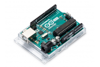
Arduino Uno...
Alkuperäinen Arduino® A000066 - Arduino Uno...
26,40 €
-
2,34 €
-
21,70 €
-
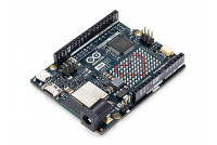
Arduino Uno...
Alkuperäinen Arduino® ABX00087 - Arduino UNO...
33,30 €
-
7,90 €


