Seeed Studio 102991442 - This CANBed-FD adopts MCP2517FD CAN Bus controller with SPI interface and MCP2542FD CAN transceiver to achieve the CAN-BUS capability. With an OBD-II converter cable added on and the OBD-II library imported, you are ready to build an onboard diagnostic device.
Ei tuotteita
CAN BUS
- 3D-tulostus
- Antennit
- Akut ja paristot
- Arduino
- Audio/video
- Autoilu
- Automaatio
- BBC micro:bit
- Elektroniikan komponentit
- Anturit
- Aktiivit
- Passiivit
- Komponenttilajitelmat
- Hälytin/valvonta
- IOT
- Juottaminen
- Juottimet
- Juotintelineet
- Juoksutteet/pastat
- Juotoslangat
- Juottamisen apuvälineet
- Kaasujuottimet
- Kuumailma-asemat
- Pintaliitostekniikka
- Puhdistustarvikkeet
- Tinaimurit ja tinaimusukat
- Varaosat Pace
- Varaosat Proskit
- Varaosat Thermaltronics
- Varaosat Velleman
- Varaosat Weller
- Varaosat Xytronic
- Varaosat Pinecil
- Varaosat Atten
- Kaapelit/johdot
- Antennikaapelit 50ohm
- Antennikaapelit 75ohm
- Audiokaapelit/johdot
- Datakaapelit
- FFC kaapelit
- Kaiutinkaapelit
- Kalustekaapelit
- Kumikaapelit
- Kuparilangat
- Lattakaapelit
- Monisäikeiset asennusjohdot
- Puhelinkaapelit
- Silikonijohdot
- Termoparikaapelit
- Verkkokaapelit CAT5/6/7
- Videokaapelit
- Yksisäikeiset kytkentäjohdot
- Kaapelilajitelmat
- Virransyöttökaapelit
- Kaapelitarvikkeet
- Kehityskortit
- Kirjat
- Ledit
- Liittimet
- Audio/video-liittimet
- Autoliittimet
- Piikkirima-liittimet
- RJ modular-liittimet
- Puristusliittimet
- RF-liittimet
- 7/16-koaksiaaliliittimet
- BNC-liittimet
- F-liittimet
- FME-liittimet
- IEC-antenniliittimet
- MC-liittimet
- MCX-liittimet
- MMCX-liittimet
- MiniUHF-liittimet
- N-liittimet
- SMA-liittimet
- SMB-liittimet
- SMC-liittimet
- SSMB-liittimet
- TNC-liittimet
- UHF-liittimet
- U.FL-liittimet
- RF-testiliittimet
- RF-välikaapelit
- Sekalaiset koaksiaaliliittimet
- Riviliittimet
- Teollisuus-liittimet
- Tietokone-liittimet
- Virtaliittimet
- Moninapaiset virtaliittimet
- DIN41612 EURO-liittimet
- Liitinadapterit
- Lämmönhallinta
- Mekaniikka
- Näytöt
- Mittalaitteet
- Yleismittarit
- Mittajohdot/liittimet
- Paneelimittarit
- Pihtimittarit
- Jännitekoettimet
- Lämpömittarit
- Ympäristön mittalaitteet
- Keinokuormat
- Komponenttitesterit
- Kuituverkon mittaus
- Sähköverkon mittaus
- Debuggaus
- Oskilloskoopit
- Signaaligeneraattorit
- Sekalaiset mittalaitteet
- Spektrianalysaattorit
- Logiikka-analysaattorit
- Probet
- Dataloggerit
- Mittalaitetarvikkeet
- Rigol oheistarvikkeet
- Rigol optiot
- Muistikortit
- Palvelut
- Puhelimet
- Protoilu
- Rakentelu
- Rakennussarjat
- Raspberry Pi
- Retro gaming
- Robotit
- Sekalaiset
- Sähkömekaniikka
- Kytkimet
- Painokytkimet
- Vandal proof painokytkimet
- Arcade pelikytkimet
- Keinukytkimet
- Liukukytkimet
- Mikrokytkimet
- Ovikellokytkimet
- Pulssienkooderit
- Rockwell teollisuuskytkimet
- Vipukytkimet
- Asentokytkimet
- Avainkytkimet
- DIP-kytkimet
- Jalkakytkimet
- Joystick
- Kalustekytkimet
- Kalvokytkimet
- Kiertokytkimet
- TV-verkkokytkimet
- Lamput
- Moottorit
- Releet
- Solenoidit
- Sulakkeet
- Tulppasulakkeet
- WICKMANN-sulakkeet
- Yleismittarisulakkeet
- Ylikuormitussuojat
- Autosulakkeet
- HRC-sulakkeet
- Lämpösulakkeet
- Langalliset sulakkeet
- Lasiputkisulakkeet
- Mikroaaltouunin sulakkeet
- Minisulakkeet TR5
- Palautuvat ylivirtasuojat
- Picosulakkeet
- Pintaliitossulakkeet
- Puolijohdesuojat
- Sulakepesät
- Sulakelajitelmat
- Kahvasulakkeet
- Termostaatit
- Kontaktorit
- Kytkimet
- Sähkötarvikkeet
- Teholähteet
- Tietokonetarvikkeet
- Tietoliikenne
- Ethernet/LAN
- RJ45-liittimet/rasiat
- Verkkokaapeloinnin työkalut
- Ethernet tarvikkeet
- Ethernet verkkokaapelit
- RJ45-moduulit
- SLIM® CAT6 Ethernet kaapelit
- SLIM® CAT6 Patchcords FLAT U/UTP
- SLIM® CAT6 Patchcords FLAT U/FTP
- SLIM® CAT6A Patchcords FLAT U/FTP
- SLIM® CAT6 Patchcords ROUND U/UTP
- SLIM® CAT6 Patchcords ROUND U/FTP
- SLIM® CAT6A Patchcords ROUND U/FTP
- SLIM® CAT6 Patchcords FLAT U/UTP with Nylon sheath
- SLIM® CAT6 Patchcords FLAT U/FTP with Nylon sheath
- Kytkentäpaneelit
- Valokuidut
- SFP Transceiverit
- WiFi
- Ethernet kytkimet
- Ethernet mediamuuntimet
- Reitittimet
- Yhdyskäytävät
- Ethernet/LAN
- TV/radio/VCR/CD
- Työkalut
- Valaistus
- Vimpaimet
- Tarjouserät
- Edustukset Elgood Oy
- Abiko
- Adda
- Arduino Pro
- Attend
- Belden
- Blueferrite
- Broadlake
- Cvilux
- Danotherm
- DECA
- Delta
- Dinkle
- Entertec
- Finder
- Finder 12 Series
- Finder 13 Series
- Finder 14 Series
- Finder 1C Series
- Finder 20 Series
- Finder 22 Series
- Finder 34 Series
- Finder 36 Series
- Finder 38 Series
- Finder 39 Series
- Finder 40 Series
- Finder 41 Series
- Finder 43 Series
- Finder 46 Series
- Finder 48 Series
- Finder 4C Series
- Finder 58 Series
- Finder 50 Series
- Finder 55 Series
- Finder 56 Series
- Finder 60 Series
- Finder 62 Series
- Finder 65 Series
- Finder 66 Series
- Finder 68 Series
- Finder 7H Series
- Finder 7L Series
- Finder 7M Series
- Finder 7T Series
- Finder 80 Series
- Finder 83 Series
- Finder 86 Series
- Finder 8A Series
- Finder 90 Series
- Finder 92 Series
- Finder 93 Series
- Finder 94 Series
- Finder 95 Series
- Finder 96 Series
- Finder 99 Series
- Fulham Company B.V
- Geehy
- Hengstler
- Hirose
- HolyStone
- Jianghai
- KDS
- Lantronix
- Linear Integrated Systems
- LinkPP
- Luminus
- Murata
- Myrra
- PeakTech
- Provertha
- Quectel
- Relpol
- Rigol
- Rigol oheistarvikkeet
- Rigol optiot
- Rigol DG800 Pro
- Rigol DG900 Pro
- Rigol DG1000Z
- Rigol DG4000
- Rigol DG5000 Pro
- Rigol DHO800
- Rigol DHO900
- Rigol DHO1000
- Rigol DHO4000
- Rigol DHO5000
- Rigol DL3000
- Rigol DM3000
- Rigol DP700
- Rigol DP800
- Rigol DP900
- Rigol DP2000
- Rigol DS1000Z
- Rigol DS2000
- Rigol DSA700
- Rigol DSA800
- Rigol DSG800
- Rigol MHO5000
- Rigol MSO5000
- Rigol MSO7000
- Rigol MSO8000A
- Rigol RSA3000
- Rigol RSA5000
- Seiko
- Sensepeek
- Sensolute
- Teltonika Networks
- Teltonika Telematics
- VAC
- Winstar
- wireless-tag
- WKK
- Uutiskirjeet
- Kampanjat
- Välitysmyynti
- Äänilähteet
- Robotiikka ja protoilu
- Virtalähteet
- Kotelot
PRODUCT DETAILS
Features
- Compact size design: 56x41mm overall dimension
- Support two CAN protocols: CAN-FD and CAN 2.0
- High-performance CAN Bus chip: MCP2517FD as CAN controller and MCP2542 (MCP2557) as CAN receiver
- Flexible CAN Interface: Industrial standard 9-pin sub-D connector or 4-pin terminal, 2 x 4-Pin Grove connectors Compatible with the Grove ecosystem
- Wide power input range from 7-28V and stable 5V/1A output
Description
CANBed FD is a CAN FD dev board with an Atmega32U4 microcontroller inside, which has 32KB of Flash and 2.5KB of RAM. The operating frequency is 16MHz, which can meet most embedded applications. There's an Arduino Leonardo bootloader inside the Atmega32U4. If you have used the Arduino IDE, programming will not be a problem for you.
CANBed FD uses MCP2517FDas CAN controller and MCP2542 (MCP2557) as CAN receiver, which are high-performance CAN Bus chips, that can work in both CAN 2.0 and CAN FD protocols at the same time. There is a Micro USB connector on the board, through which you can program the board or supply power to the board. There is one I2C, one UART, one SPI interface, 3 analog input interfaces, and 8 digital IO on the board.
This CANBed-FD Arduino CAN-FD Development Kit adopts MCP2517FD CAN Bus controller with SPI interface and MCP2542FD CAN transceiver to achieve the CAN-BUS capability. With an OBD-II converter cable added on and the OBD-II library imported, you are ready to build an onboard diagnostic device.
What's more, the is an ATmega32U4 with Arduino Leonardo bootloader on the board, you can use Arduino IDE to program the board easily.
Learn more about CAN-BUS here.
Specification | Details |
|---|---|
| MCU | ATmega 32U4 (with Arduino Leonardo bootloader) |
| Clock speed | 16MHz |
| Flash memory | 32KB |
| SRAM | 2.5KB |
| EEPROM | 1KB |
| Operating voltage | 7~28V |
| Input interface | Sub-D |
Hardware Overview
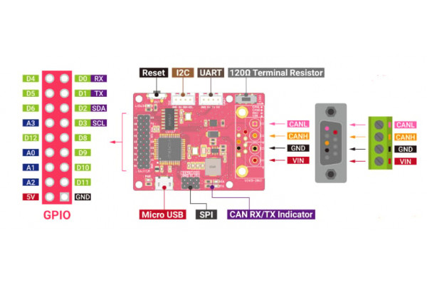
- GPIO - 9x2 I/O Pin OUT
- Micro USB connector for programming
- SPI - ICSP connector
- CAN RX/TX Indicator
- DB9 connector or Terminal for CAN Bus
- Switch for the 120Ω terminal resistor for CAN Bus
- Grove connector for UART
- Grove connector for I2C
- Reset
Part List

| CANBed PCBA | 1 |
| Sub-D Connector | 1 |
| 4-Pin Terminal | 1 |
| 4-Pin 2.0 Connector | 2 |
| 9x2 2.54 Header | 1 |
| 3x3 2.54 Header | 1 |
Links
| Klikkaa tarkemmat tiedot | |
| Valmistaja | Seeed Studio |
| Valmistajan malli | 102991442 |
| Prosessori | AVR (ATMEGA32U4) |
Tätä tuotetta ostaneet ostivat myös:
-
13,00 €
-
36,50 €
-
Grove CAN...
Seeed Studio 114992978 - Grove - CAN BUS Module...
13,76 €
-
7,90 €
-
Raspberry Pi...
Joy-IT rb-camera-WW - Raspberry Pi...
40,37 €
-
LUKITUSRUUVI...
160-osainen sarja 12:a eri kokoa
12,70 €
-
40,10 €
-
22,50 €


